Versorgungsanlagen im „Fuchsbau“
Der Dispatcherraum im „Neubau“ TO-01
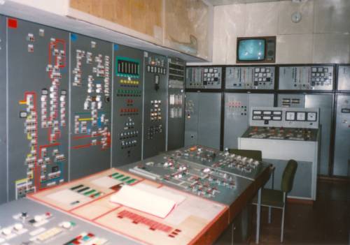
Vom Dispatcherraum im 2. UG wurde die komplette technische Versorgung des Schutzbauwerkes mit seinen über 190 Räumen für die verschiedenen Betriebsarten gesteuert und überwacht.
Das Schleusen beim Betreten und Verlassen steuerte von hier der Dispatcher.
Jedes Bauwerk war außerdem in mehrere, hermetisch voneinander getrennte Brandabschnitte aufgeteilt, deren Zentrale hier war.
Hier liefen auch die Steuerungen für die Strom-, Luft-, Wasser- und Abwasserversorgung der Bunker zusammen.
Von externen Tiefbrunnen wurde aufbereitetes Kühlwasser ins Bauwerk gepumpt und hier kontrolliert.
Auch die Hochspannungssicherungsanlage um den eigentlichen Bunkerbereich wurde von hier bedient.
Links im Bild der Schaltschrank zur Umsteuerung der Betriebsweisen I, II und III.
Im Hintergrund die Netzersatzsteuerung für die 4 Dieselaggregate, die über einen in der Bunkerdecke eingebauten Massekühler Verbrennungsluft auch bei Napalmangriffen ansaugen konnten.
Rechts im Hintergrund der Schaltschrank für die Außenluftüberwachungsapparatur DAU, die bei Grenzwertüberschreitungen eine automatische Betriebsartensteuerung der Bauwerkshermetisierung ermöglichte.
Neben einem zivilen ESER-Großrechersystem EC-1056 zur Gefechtsvorbereitung im GA-V, mit einer eigenen Klimaanlage ausgestattet, waren weitere umfangreiche technische Anlagen zur Sicherstellung des automatischen Betriebes im Schutzbauwerk untergebracht.
So vier Schiffsdieselaggregate zur Notstromversorgung, eine automatische Netzersatzanlage, drei Umformergeneratoren zur Erzeugung von 400Hz-Wechselspannung, ABC-Luftfilteranlagen, sowie mehrere Systeme zur Kühlung, wobei anfangs das aus eigenen Brunnen gewonnene Kühlwasser in den nahen Petersdorfer See abgeleitet wurde. Ab 1983 sorgte eine externe Kühlanlage für die Ableitung der Wärme im Bauwerk, wo in den technischen Räumen die Temperatur bei 28 °C lag.
Die Wasserversorgungsanlagen des TO-01
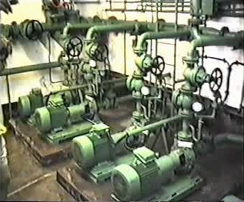
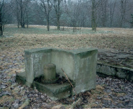
Im 2. Untergeschoss der Raum mit den Pumpen für die Kühlwasserversorgung des Bauwerkes aus 3 Vorratsbehältern. Im Notfall konnte Wasser aus eigenen Tiefbrunnen mit einer Temperatur von rund 8°C ins Bauwerk gefördert und hier aufbereitet werden.
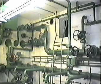
Über die Leiter und den Mauerdurchbruch konnte man in die Kühlwasservorratsbehälter gelangen.
Das im Klimablock erwärmte Wasser wurde von hier über eine eigens angelegte Kanalisation in den Petersdorfer See geleitet.
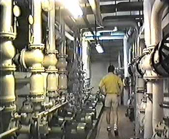
Da die Kühlung mit Brunnenwasser sehr kostenintensiv war, wurde das Wasser schließlich mit Hilfe von externen Kühlkompressoren im geschlossenen Kreislauf auf die erforderliche Temperatur abgekühlt.
Luftversorgungsanlagen im TO-01
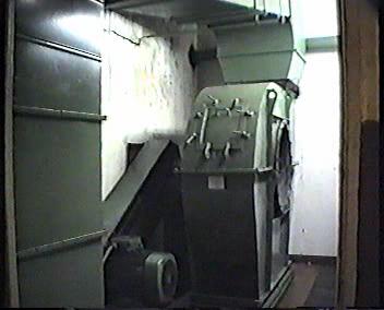
Riesige Ventilatoren saugten pro Stunde 40.000m³ Bauwerksluft an und beförderten sie durch mehrere Filtersysteme und die 3 Klimablöcke in alle Arbeitsräume.
Die Fortluft wurde über die Druckklappe nach außen geleitet.
Sanitär-, Küchen- und Abfallräume werden gesondert belüftet.
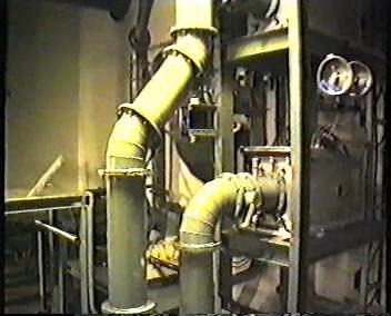
In den Kammern der Zuluftanlage waren Filter unterschiedlicher Zweckbestimmung verbaut.
Eingesetzt wurden Staubfilter, Absorptionsfilter, Geruchs- und thermokatalytische Filter, sowie in einzelnen Räumen Regenerierpatronen.
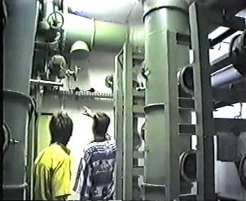
Je nach gefahrener Betriebsweise wurde über diverse Motorschieber die Atemluft in die entsprechenden Filtersysteme geleitet.
Bei Normalbetrieb wurde Außenluft durch Grobstaubfilter und nach außen geleitet.
Während des Schutzbetriebes wurde die Außenluft zusätzlich durch Vor- und Absorptionsfilter gesaugt.
Im Hermetisierungsfall wurde nur Umluftbetrieb mit Überdruckhaltung gefahren. Dabei gab es keine Be- und Entlüftung.
Die Notstromversorgung im TO-01
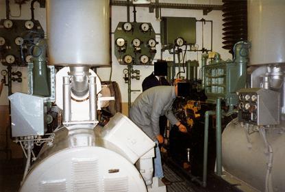
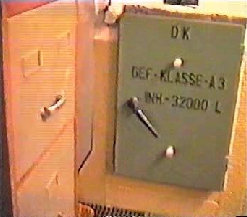
Im 2. Untergeschoss befindet sich der Raum mit den vier Schiffsdieselmotoren der Notstromversorgung für das Schutzbauwerk.
Immer vorgewärmt, starteten sie automatisch bei Netzausfall und waren nach 20 Sekunden einsatzbereit.
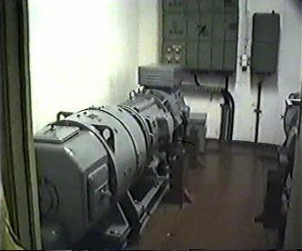
Ebenfalls im 2. UG befindet sich der Raum für die zwei Aggregate der unterbrechungsfreien Stromversorgung für ausgewählte Verbraucher.
Hier im Bild das sowjetische System UGP-50.
Die Versorgung mit Elektroenergie erfolgte aus zwei separaten Landesnetzen von Fürstenwalde und Petersdorf.
Der Anschlußwert lag bei 2000 kW.
Die Transformatoren befanden sich außerhalb des Bauwerkes.
Für die Versorgung des Führungssystems „ALMAS“ mit 400Hz-Spannung sorgten drei Umformergeneratoren im Verteilerraum.
Ein Umformer war immer in Betrieb.
Bei Alarmauslösung wurde ein weiterer zugeschaltet.
Das 3. Aggregat konnte als Reserve wahlweise genutzt werden.
Der Dispatcherraum im Schutzbauwerk des „Altbau“ TO-02
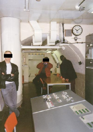
Hier befand sich bis 1976 die alte Netzersatzanlage des Bauwerkes.
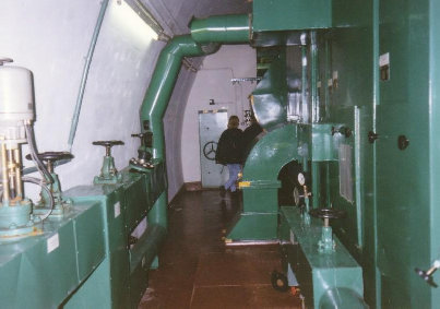
Der Speiseraum im Altbau
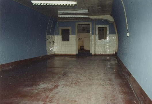
Hier standen Vierertische für Soldaten, Unteroffiziere und Offiziere.
In der Ecke hing unter der Decke ein TV-Gerät.
Die Lüftergeräusche der Klimaanlage waren aber deutlich kräftiger, so dass es kaum Zuschauer gab.
Im Hintergrund sind die Küchenräume des TO-02 zu sehen.
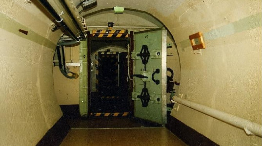
Es soll Leute gegeben haben, die in der Schleuse beteten, dass die Tür auch wieder aufgeht und die Wechselsprechanlage funktioniert...
